In the past 2 days,
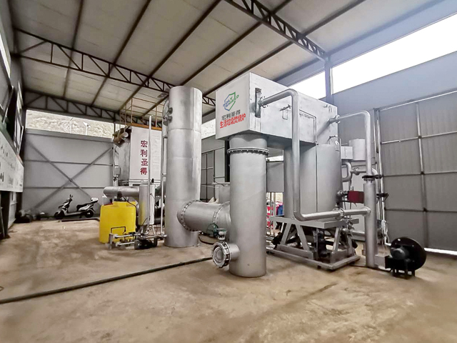
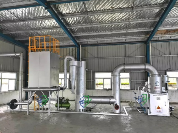
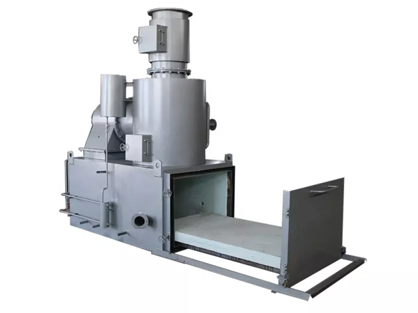
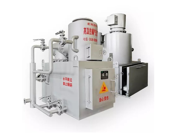
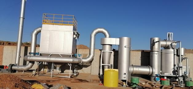
Holy Shield explained the technology and advantages of resource utilization method waste incinerator. Today, based on real engineering cases, we will show you the system design scheme of the incinerator.
1. Feeding design of incinerator
①Main function
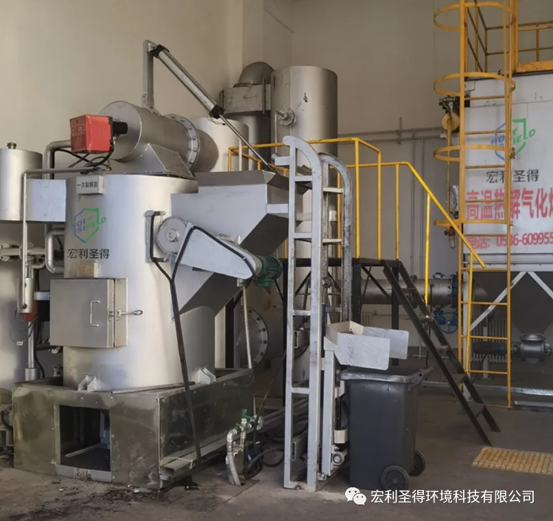
The feeding device consists of a feeding device, an incinerator cover, and a feeding port.
The incinerator cover is composed of steel structure and refractory material. On the one hand, it prevents heat from dissipating, and on the other hand, it acts as a safety valve during unstable gasification. It has the characteristics of compact structure, small size, light weight and convenient operation. When the material is loaded, the furnace cover is automatically opened, and after the material is loaded, the furnace cover is automatically closed. The feeding device is composed of a hopper car, a lifting frame, a pulling hanger, etc. When feeding, the garbage is poured into the hopper, the furnace cover is automatically opened first, the hopper truck rises, and it is automatically poured into the furnace. This feeding method is especially suitable for medium-sized incinerators, and has many advantages such as good sealing, convenient feeding, convenient maintenance and low cost. If other mechanical or hydraulic feeding is used, more auxiliary materials are required, the cost is high, there are many failures, poor maintenance, and long maintenance time. After a comprehensive comparison, we adopt the above-mentioned feeding method, which is also one of the scientific and technological successes of Holy Shield.
②Main technical parameters
Feed hopper size: a×b×c=1×0.8×0.8m
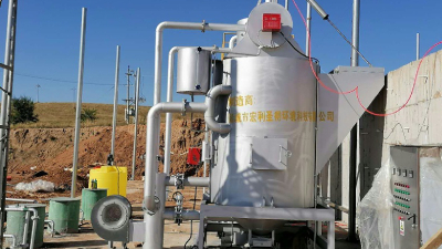
2. Resource utilization method incinerator design
①Main functions
The
resource utilization method incinerator is based on the principle of pyrolysis and gasification and the three elements of material combustion, and adopts a fuzzy method to burn, gasify and dehydrate the waste under closed conditions, so that the carbon material in the waste is partially burned and decomposed to generate Combustible gases such as carbon monoxide, hydrogen, methane and other carbohydrates are mainly used to achieve the dual purpose of incineration of garbage and generation of combustible gases without the use of auxiliary fuels such as diesel, heavy oil and natural gas.
Since diesel oil, heavy oil and natural gas are not used for incineration, it not only saves energy, but also uses combustible gas in the oxidation tower behind the furnace to incinerate the flue gas, so that the toxic and harmful substances in the flue gas can be completely eliminated under high temperature conditions. The flue gas after high temperature oxidation is finally discharged into the atmosphere better than the national standard after quenching heat exchange and exhaust gas purification.
(②Requirements for some technical parameters of the incinerator
Fuel consumption: no fuel, fuel consumption is 0;
Water consumption: no water, water consumption is 0;
Gas consumption: no gas, gas consumption is 0;
Power consumption: 4kw;
5000kg/d resource utilization method incinerator volume: 28.628;
Effective geometric size: φ×H=φ2700×5000;
Dimensions: φ3300×5700.
③Blower: Oxygen in the air supplied by the blower combines with the combustible components in the garbage under certain temperature conditions, that is, combustion, which is one of the functions of the blower; the second function is that the incinerator does not vibrate or rotate the grate. For better combustion, the incinerator adopts a special structure, which uses the air blown by the blower to move the garbage, so that the garbage can be completely burned. Blower model: 9-26N04A4kw.
3. Combustion chamber design
①Main functions
The function of the combustion chamber is to fully mix and combust the combustible gas and tail gas resources generated by the waste incinerator with air, and play a combustion-supporting role in the initial stage of waste gasification and ashing and cooling.
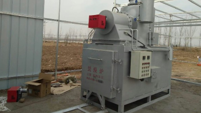
②Burner: Generally, a two-stage light oil burner is selected. If the conditions are good, a natural gas burner can be used.
③Main technical parameters
Fuel consumption or gas consumption: The fuel consumption or gas consumption is low. When oil is used, the fuel consumption per hour is 3-6kg. If gas is used, the gas consumption is 6-20m3 per hour (for oil injection and gas injection, only choose the other one. one);
Power consumption: less power consumption, 0.37kw;
Water consumption: no water, water consumption is 0;
Effective geometric size: φ600×800
Dimensions: φ900×1000
4. Design of oxidation tower
①Main functions
The resource utilization method oxidation tower is designed according to the swirl double back combustion technology and the three elements of temperature, time and eddy current. The tower can automatically enter the gas and fire together with the combustible gas generated by the waste in the resource utilization method incinerator together with the flue gas. Under the effect of combustion support, the indoor temperature rises rapidly to 850-1100 °C, so that all the combustible gases in the flue gas will spontaneously ignite. High-temperature oxidation and strong decomposition of various organic gaseous, liquid, solid and other harmful substances in the tower are realized. After any flue gas and toxic and harmful waste gas are treated by the tower, the incineration rate reaches 100%.
②Technical parameters
The oxidation tower adopts a special structure type to meet the "3T" principle of waste incineration.
The effective geometric size of the oxidation tower: φ×H=1400×8700.
Dimensions: φ2000×9000.
Fuel consumption: no fuel consumption, fuel consumption is 0;
Water consumption: no water, water consumption is 0;
Gas consumption: no gas, gas consumption is 0;
Power consumption: no power consumption, power consumption is 0;
5. Quench tower
① Main functions
After the combustible gas and other flue gas produced by the waste incinerator enter the cyclone compound oxidation tower, under the condition of high temperature, all the harmful substances in the exhaust gas are oxidized, and the air flow discharged after oxidation has a high temperature. The high temperature flue gas is cooled first, and then the exhaust gas temperature is lowered by cyclone spraying and quenching. The clean hot water in the inner pipe of the cooler can be used for bathing and utilizing energy. It is more reasonable to use the method of quenching after cooling to protect the subsequent equipment.
②Technical parameters
Effective geometric size: φ×H=φ1400×7500H.
Quench tower technical index requirements:
Fuel consumption: no fuel, fuel consumption is 0;
Power consumption: no power consumption, power consumption is 0;
Water consumption: The drainage is treated as reclaimed water, and the water consumption is regarded as 0;
6. Design of four-stage tail gas purification tower
①Main functions
The exhaust gas purification tower of the
resource utilization method incinerator adopts purification technologies such as circulating spraying, washing flue gas, gas-water separation, and activated carbon adsorption, which thoroughly purifies the flue gas during the incineration process of garbage, and the purification results are better than the national emission standards. It is also a major feature of environmental protection.
The exhaust gas purification tower has compact structure, reasonable design, small footprint, low operating cost, low investment, long service life, reliable operation, convenient management and low maintenance cost. It is an ideal equipment for exhaust gas purification after waste incineration.
The flue gas is fully contacted with the spray circulating water in the strong rotation, and is fully contacted and efficiently mixed under the action of centrifugal force, which promotes the increase of the weight of the light dust in the exhaust gas, realizes the separation of gas and dust, and achieves the purpose of first-level purification. After the first-level purification, under the action of gravity, it enters the second-level spray atomization chamber again, which also forms full contact and high-efficiency mixing, which increases the weight of the dust again, further realizes the separation of gas and dust, and achieves the separation of exhaust gas in gas and water. After the chamber is separated from gas and water, it automatically enters the activated carbon adsorption chamber for adsorption, and the pollutants in the exhaust gas are basically removed, so that the exhaust gas meets the international standard and is ejected into the air by the induced draft fan.
②Main technical parameters
Geometric size: 5000×2500×3000H
Fuel consumption: no fuel, fuel consumption is 0;
Power consumption: small power consumption;
Water consumption: the dust removal is used in a closed-circuit cycle, and the water consumption is regarded as 0;
Gas consumption: no natural gas or gas consumption, gas consumption is 0;
7. Induced fan
①Main function
The exhaust gas is ejected to make the entire incineration system run at a slight negative pressure.
②Main technical parameters
Model: Y5-47№5C, right 90°, air volume 4723~8909m3/h, wind pressure 2324~1687Pa, 7.5Kw.
8. Chimney
①Main function
High-altitude exhaust airflow
②Main technical parameters
Chimney diameter φ500;
Chimney height ≥ 25 meters.
9. Design of electrical control system
Main function
In order to improve the efficiency and safety of the incinerator, we use automatic control to monitor and display important parameters of the incinerator system such as furnace temperature, and realize full (semi) automatic control of the incineration system through the monitoring value. There are operation panels, display instruments, etc. on the operation table.
The incinerator can realize automatic temperature control. By controlling the fuel consumption of the burner, the temperature of the combustion chamber can be kept within the preset upper and lower limits; the combustion chamber is equipped with a temperature detection element, and the detection element sends a signal to the control The indoor temperature display instrument, when the temperature is lower than (or higher than) a certain value (the set value can be modified), and this value is input into the control system as an analog signal to issue commands to control the two solenoid valves of the burner , and then control the temperature of the combustion chamber (it should be noted that the higher the temperature, the better, but to minimize the fuel consumption while satisfying the processing effect).
In addition, temperature measurement points are set at the inlet and outlet of the water heat exchanger on the flue behind the water heat exchanger and in front of the dust collector to control the operating state and protect the equipment's working conditions within the design range.
10. Sampling hole
A permanent sampling hole (GB/T1657) is set on the exhaust pipe.
11. Others
The whole set of equipment has high processing efficiency, safety and reliability; the flue gas purification adopts serial exhaust gas purification, which has high processing efficiency, simple equipment flow, and low maintenance and management costs; the combination of automatic equipment operation and manual labor improves system stability and reduces labor intensity. , Strengthening the rationalization of investment; compact equipment layout, high and low levels between equipment, less land occupation, and low infrastructure costs.
